
Please scroll to see all 8 drawings and descriptions.
In Fig.1 a simplified application is shown of the geometric law that a straightedge orbiting an ellipse describes a circle. A rotor (1), here shown an ellipse, rotates around an axis (2), and contacts two pivoting bodies (3), that pivot around their axes (4) inside a housing (10).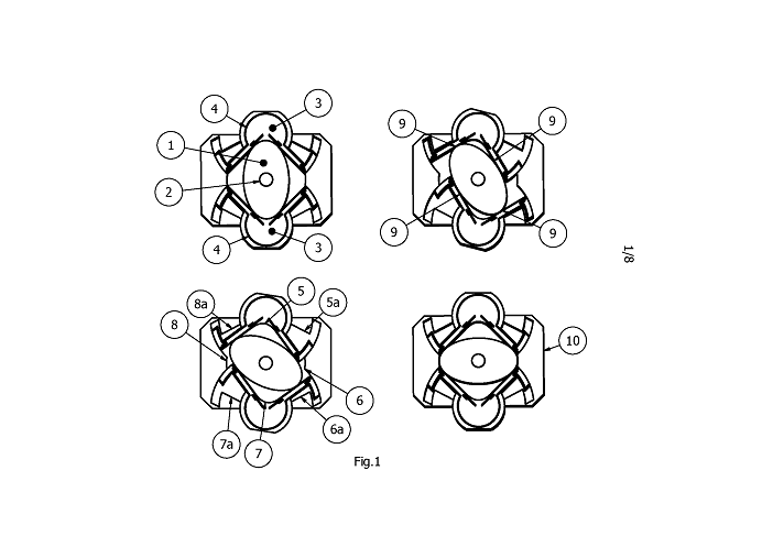
For an ellipse, with major semi-axis t and minor semi-axis s, it can be shown that a pivoting straightedge, centered at a distance of squareroot{ t squared plus s squared} will always have two, and only two contact points (9). As shown here, it is sufficient that the pivoting body has a straightedge shape only on the contacting path with the ellipse. In this way, four expanding and compressing internal volumes (5), (6), (7) and (8) are created, which can be filled or emptied through openings in the rotor, the straightedges, top or bottom. Additionally four secondary expanding and compressing volumes are created (5a), (6a), (7a) and (8a), between the housing and the straightedges. Here shown are four stages of one quarter of a rotor rotation, in which top and bottom volumes (5) and (7) expand from minimum to maximum, right and left volumes (6) and (8) contract from maximum to minimum, secondary volumes (5a) and (7a) are first expanding and then contracting, and secondary volumes (6a) and (8a) are first contracting and then expanding. Mirroring and reversing the order of the pictures can easily show the other three quarters of the rotor rotation. Applications can be for instance as pump, compressor, steam or Stirling engine.
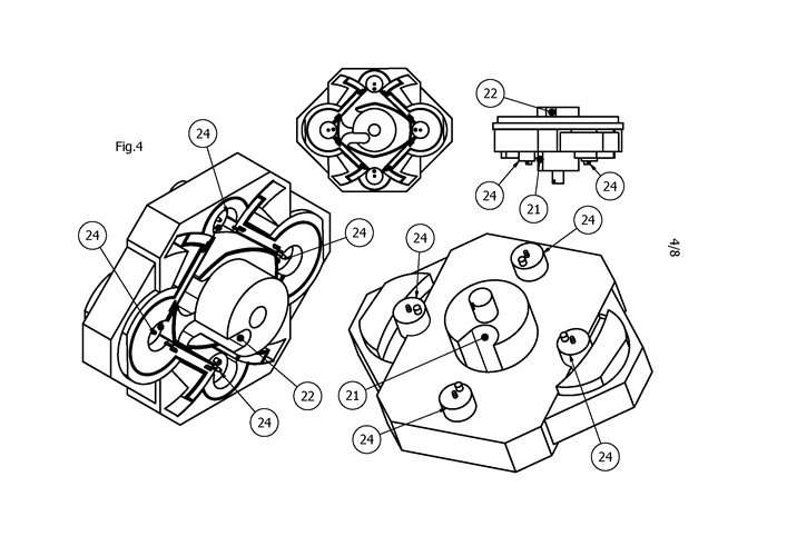
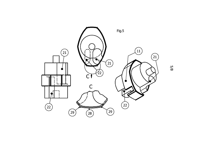
In Fig.2 a possible application is shown with a non-elliptical rotor (11) with inlet (21) and exhaust (22). The rotor has a bearing (12) and the pivoting bodies (13) have bearings (14) and are rotating inside the housing (20). They create volumes (15), (16), (17) and (18), and secondary volumes (15a), (16a), (17a) and (18a). The contact areas on the pivoting bodies here are made of separate glide plates (19) that act as mating surfaces for the rotor material, and act as sideway seals to compensate for manufacturing tolerances and wear. Inside the housing (20) and pivoting bodies (13), and through the bottom of housing (20), cylindrical bodies (24) are inserted, which can move along their axis, and which can change the expansion ratio’s of volumes (15), (16), (17) and (18). 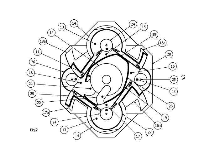
In, on, or instead of these bodies (24), spark plugs (25), fuel injectors (23), valves and other devices can be inserted, for instance to facilitate venting, inlet/exhaust timing, ignition timing, addition or recirculation of gasses or fuel. Next to the glide seals (19), each primary volume (15), (16), (17) and (18), is sealed from the top and bottom by seals on the housing (26), pivoting bodies (27) and rotor (28), pressed down by the top seal (31) and body (33) (as shown in Fig.7). Lubricating oil is supplied to the gliding plates by bodies (29) or from inside the pivoting body (13). Cooling and lubricating fluid can be transported in the rotor (11) through the bearing (12) radius, inside the pivoting bodies (13) through their bearing (14) radii, and inside the housing (20). Additional (e.g. steam) cooling can be applied through the secondary volumes (15a), (16a), (17a) and (18a), possibly creating additional power, and possible air cooling along the rotor(11) axis, heat pipes and cooling fins. Bearings can be large, long and robust to accept fast combustion. Concatenation of units can minimize vibrations. Application for instance as Controlled Auto Ignition (HCCI) combustion engine.
Half a rotation is shown of the configuration of Fig.2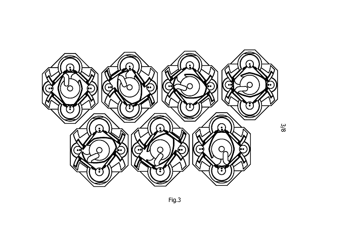
The glide plates (19) are inserted into recesses, where they can move within the recesses, and be pressurized externally or through openings (30) by combustion gasses.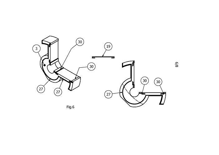
If tolerances allow, a fixed top plate (33) is sufficient. Otherwise, the top plate (33) and seal (31) can co-rotate with the rotor and take up axial tolerances and wear. In this case a small hole (32) can be used, allowing high pressure combustion gasses to enter, to pressurize the seal downwards towards the rotor, pivoting bodies and housing.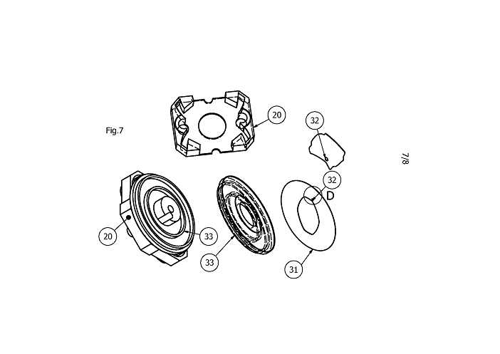
In Fig.8 a rotor (41) is shown, its boundary being made up out of (infinitesimal) sections of ellipses (x*x/t*t +y*y/s*s = 1, with t*t+s*s=R*R, on which a inscribed rectangle (46) can be defined, such that (a,b), (-a,b), (a,-b) and (-a,-b), lie on the boundary, with a+b=R, with R the distance between center points of rotor and pivoting body.
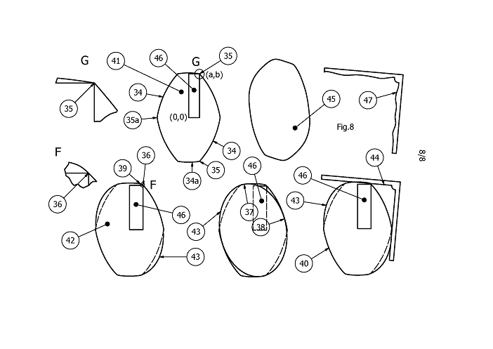
The boundary curve of the rotor has a continuous mapping of a normal vector n, (–pi< angle(n) <= pi) to the angle of, the origin based, vector m of a boundary point (–pi< angle(m) <= pi), where the mapping can be bijective (one-to-one) as on point (36) of rotor (42), or surjective (one-or-more-to-one) as on point (35) and (35a) of rotor (41). In either case the boundary can be cut up into connected smooth sections (34) and (34a), and the direction of rotation of the normal vector n follows the direction of rotation of m on the boundary curve. In effect, the straightedge is the operator, mapping one section (34) on the next section (34a), and this section (34a) on the next (34), continuing back to the first section. This means shapes will be point symmetric (45) and for any given phi, a part of a boundary curve with m defined for phi<angle(m)<=phi+pi/2 defines the whole boundary curve.
Shown further is an ellipse (43), which could be defined for any point of the boundary curve, by the point and its normal vector (37) and a perpendicular normal vector (38) at another point on the boundary. This meaning a straightedge (44) would contact these points precisely. Within some mathematically definable boundaries, tolerances and some curvature can be allowed on the straightedge (47), which will slightly differently map one point on the boundary, to another point on the boundary. A remaining property is that, on each arm of the straightedge, a plane through the pivoting axis and any contact point at distance sqrt(2)*a will go through any contact point at sqrt(2)*b, and the planes of the two arms are perpendicular. Even though approximate, the rotor will now not be made up out of (infinitesimal) ellipses as describe above, but will be close.